Common properties of nodes
The nodes will always have outputs that will be connected to the inputs of other nodes. They may also (and will probably) have parameters that can be modified in the user interface, and inputs to receive data from other nodes.
Outputs
Nodes can have several outputs that represent the data they provide. Each node output can be connected to several node inputs. Each node output (and input) can be:
a grayscale image (shown in grey)
a color image (shown in blue)
an RGBA image (shown in blue)
a 2D signed distance function (shown in orange)
a 3D signed distance function (shown in orange-red), with or without a color index
a color or grayscale 3D texture (shown in violet), that can be associated to a color index, which makes it possible to associate several 3D textures in a single 3D scene
Fill information (shown in green), that contain the bounding box of the area. This information is generated by the Fill node and a few pattern nodes, and is used as input by the Fill companion nodes
Greyscale, color and RGBA inputs and outputs can be connected to each other and will automatically be converted when required.
2D signed distance functions have a specific preview that shows the associated signed distance field. They can be converted into grayscale images using the sdShow node.
3D signed distance functions have a specific preview that shows the lit 3D scene. They can be converted into a grayscale height map and a color normal map using the Render node.
3D textures are previewed on a sphere
Clicking on an output slot will show the corresponding preview at the bottom of the node. When a node has several outputs, only one of them can be previewed at a time. The previewed output slot will have a circle around it, and clicking it again will hide the preview.
Inputs
Inputs (if any) can have the same types as outputs. An input is always connected to at most one output. Inputs generally have a default value that is used when it is not connected.
Parameters
Parameters are used to configure nodes. The following types are supported:
float parameters are used whenever a real number is needed. Float parameters have bounds, but it is possible to ignore them (at your own risk). To modify a float parameter, click in the text field and enter a new value, or click and drag left or right to decrease or decrease its value. When the lower or upper bound is reached, the value will stick to it, but dragging again from there makes it possible to go beyond the limit.
In most cases, float parameters also support expressions (written in GLSL syntax), where other parameters and named parameters are accepted and must be prefixed with a dollar sign. This feature is useful when two parameters of the same node must depend on each other, or when several parameters of several nodes of a subgraph must be calculated from one or more named parameters.
The $time variable can also be used in parameter expressions to define animations in generated shaders, but generated Static PBR Materials will still be static (this feature could for example be used to export variations of the same material). Other predefined material types can fully benefit from this feature.
Randomness can be added to any node by using the $rnd(min, max) function, that will generate a random number between min and max. The node’s seed can then be modified, copied or locked using the die button. Alternatively, $rndi(min, max) will generate a random integer between min and max (inclusive).
Right clicking a float parameter field will show an expression editor, that checks the syntax of the expression. Whenever the expression is incorrect, the Apply and OK buttons will be disabled. You can still use the Enter key to apply the changes if necessary.
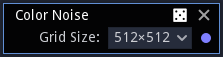
size parameters are power of two values for the image size. They are used when actually storing data in a texture, or when performing resolution dependent calculations such as convolutions. They are shown as drop down list boxes.
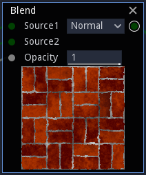
enumerated parameters are used when nodes have different named options and shown as drop down list boxes.
boolean parameters are shown as check boxes.
color parameters are shown as Color selectors.
gradient parameters are edited in dedicated editor widgets. Cursors can be added by double-clicking in the lower part of the widget, dragged left and right using the left mouse button, and removed using the right mouse button.
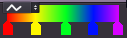
The drop down list box can be used to select one of the 4 interpolation options.
Double clicking in the upper part of the gradient editor will open a larger version of the widget to move cursors mode precisely.
Finally, it is possible to drag and drop from the upper part of a gradient editor widget to another to duplicate the gradient parameter, or from any Colorize node variant in the library to a gradient editor widget.
curve parameters are edited using a dedicated dialog window that is shown when clicking on the parameter.
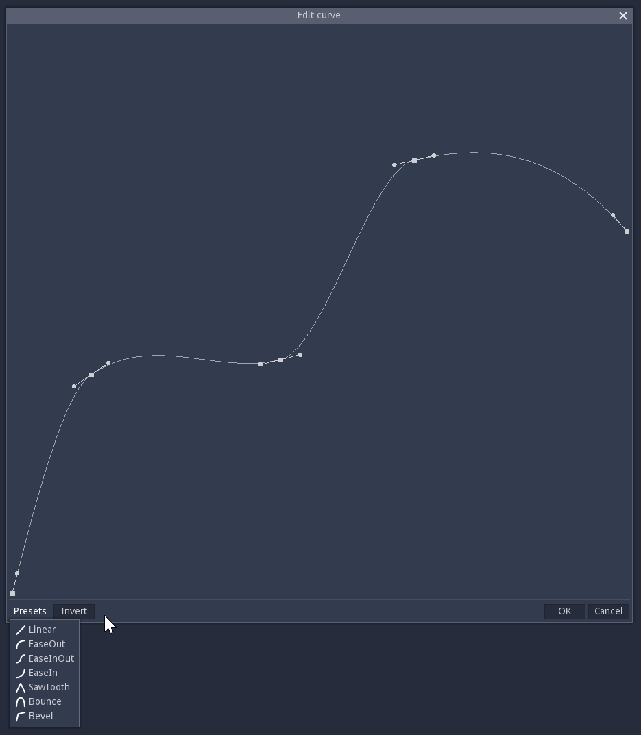
The curve is defined by its control points that define their value and left and right slopes for given abscissas. Control points (as well as slope control points) can be grabbed and moved using the left mouse button.
New control points can be added by double-clicking in the editor, and control points can be removed using the right mouse button.
The curve editor comes with a selection of presets available in the Presets menu and an Invert button to invert the curve. Presets included are: Linear, EaseOut, EaseInOut, EaseOut, SawTooth, Bounce and Bevel.
polygon parameters are edited using a dedicated dialog window that is shown when clicking on the parameter.
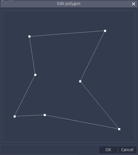
The polygon parameter is defined by its vertices that can be grabbed and moved using the left mouse button.
New vertices can be created by double-clicking in the editor (when created, a new vertex will be used to split the closest edge), and deleted using the right mouse button.
Randomness
Nodes that provide random patterns have an implicit seed parameter. It is not possible to edit it directly, but clicking the small die button in the node’s title bar will change its value. Right clicking this button will show a context menu that can be used to copy and paste the seed as well as lock and unlock it. A node with locked seed will not be affected by its parents and will have the same seed in all variations.
Subgraphs also have their seed and transmit it to their children unless not configured to do so, or the children’s seeds are frozen.
Variadic nodes
Nodes can have a variable number of inputs, parameters and outputs depending on the context.
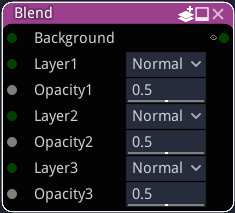
Such nodes have a specific icon in their title bar. Clicking tht icon with the left mouse button will increase their variadic size, and the right mouse button will show a menu with the minimum size (depending on current connections) and a few other choices.
The variadic size of the node in the number of instances of its variadic parameters and ports.
Modifying nodes
Most nodes in Material Maker can be modified, but they first have to be made editable. To do this, select a node, and use the Tools -> Make the selected nodes editable menu item or the Control+W keyboard shortcut.
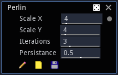
When made editable, 3 buttons are shown at the bottom of the node:
A pencil-shaped button to edit the node (the precise behavior of this button depends on the node type)
A folder-like button to load an existing node template
A floppy disk button to save the node as a template
Loading and saving templates are only useful when contributing new nodes for Material Maker. Modifying your Material Maker installation may break compatibility with existing materials, and is not recommended unless you know what you are doing.
To be reusable directly, templates must be saved in the generators directory in the install dir (or the addon/material_maker/nodes directory when using Material Maker as a Godot addon). All nodes templates saved in this directory are shown in the Tools -> Create menu.
It is not recommended to save newly created nodes as templates, but this makes them a lot easier to access and results in smaller material files (only references to the templates are saved and not the whole node description). Consequently, modifying a template without ensuring compatibility with the old version (i.e. removing or renaming parameters, removing or swapping inputs or outputs) may break existing materials, and should thus be avoided.